After a series of considerations and theoretical analyzes contained in the first part of the cycle, the time has come for design work and prototypes.
First of all, I focused on proper dimensioning based on the elements that I planned to use during construction, including the construction of the frame from Krokus enlarger and the cassette from the Polaroid SprintScan 45 scanner. The light source was to be built as a lamp based on LEDs.
After determining the distance and dimensions, the first prototype was prepared based on the materials available in the garage, i.e. plywood, wooden slats, screws, carpenter’s glue and matte black paint. The resulting enlarger head didn’t look visually appealing, but surprisingly worked. And, no, I will not put its photo, because leading internet search engines will index it as the main visual element illustrating this post and no one will want to go in and read its content ;-).
Satisfied with the first results… I put the project on the shelf. I came back to it after “inspiration came to me” and decided to finish it in a new form. In the meantime, I revised my views on the design itself and came to the conclusion that I no longer like the current shape of the head. The new version was to get a completely new look, this time realized in the form of 3D prints.
This approach allowed better adjustment of the whole to the finished elements and expanded the range of possibilities when it comes to shaping their appearance. It also fits quite neatly into the trend of designing and building photographic equipment that uses the high availability of tools for rapid prototyping.
Head – initial assumptions
I decided to build a diffusion head because a condenser head would require large, and very expensive, condenser lenses. The diffusion head is not only simpler in construction, but also significantly expands the range of possibilities when it comes to light sources. In addition, being the owner of one in the LPLu 7700, I know that it allows you to minimize the impact of scratches and imperfections of the negative material. The downside may be the lack of sharp grain on the finished print, but hey, do you think that for a 18×24 centimeter, which is equivalent to a 2x magnification on a 4×5 inch negative, it would be visible? For comparison, a similar format of a 35mm negative print is almost seven times enlarged.

Construction of diffuser and condenser enlarger.
The whole concept of such a head is based on dispersing the light coming from its source as evenly as possible using several techniques. The first one is the reflection from the white, matte surfaces forming the walls of the diffuser chamber. The second passing through the focusing screen, or milk glass, located directly above the photosensitive material.
And here’s an important point. The screen must be sanded with a very fine grain, smooth, without any scratches that could be found in the depth of focus of the enlarger lens and cause them to be registered on the print as shadows or lines. Milky glass must also be matt from the negative side, so that the “ghost” effect does not arise as a result of the reflection of the image from the photosensitive material on its surface.
Source of light
In the original variant, the light source was planned to use LED strips with adjustable color, which basically was a way to get the construction of a multi-gradation head. Unfortunately, it turned out that the obtained light power, further reduced by the need to use two sheets of milky material to disperse the light points, meant long exposure times. There were also problems with the uniformity of the resulting lighting. Of course, it would be possible to increase the number of diodes and their power, but in the end, assuming that I mainly use solid-grade papers, it seemed to me of little importance. Optionally, you can always redesign the head to equip it with a drawer for gel filters. The topic of building your own light source has therefore been postponed to an unspecified future.
Finally, I decided to use Andoer panels based on 124 microLEDs with adjustable power and color temperature in the range of 3300 to 5600 Kelvin. The regulation itself could potentially give a substitute for working with multigrade paper, but I suspect that it is not very satisfactory. Maybe I’ll check it sometime. The lamp shines with the entire surface, quite evenly with a power of about 13 watts and is powered by a 9V power supply (I suggest at least 2A one). It also turns on immediately, which is of great importance for the correct adjustment of the exposure time.
The size of the lamp dictates the shape of the head, which I decided to insert without additional fastening. Of course, this approach must be changed if you plan to make very large enlargements with projection onto the wall, but in this situation the panel itself will definitely have too little power.
Head – design
Knowing the theoretical premises presented in the first part and the technical limitations resulting from the fact that the medium format enlarger is the basis for our construction, we can proceed to the design of individual parts of the head.
The lower element located below the negative cassette is a chamber, which, by adding distance from the bellows attachment, allows the projection of a much larger image from the negative than was originally possible.
This element is 60mm and causes the negative to be moved approximately that much from its original position.
The whole, together with the guide for the cassette and the fastening element to the original construction of the enlarger frame, consists of three parts printed separately and then glued together. In the first version, the elements were split into two, but for various reasons, this has been modified to the current form.

Spacer chamber and cassette guide.
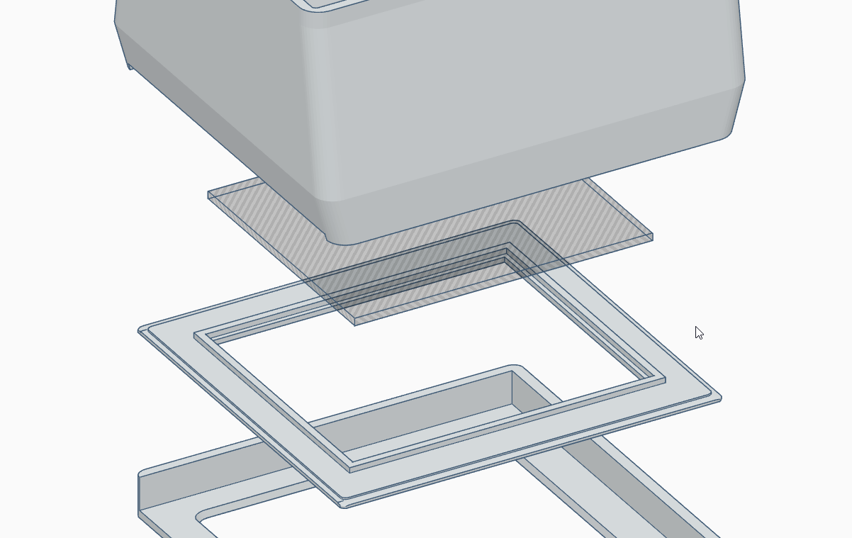
Above the chamber and the cassette guide there is a diffuser consisting of three elements. These are the casing, the focusing screen frame and the focusing screen itself, respectively. The whole thing is glued together.

Diffuser design.
The sizes of individual cutouts are selected so that the light falling on them does not cause additional reflections or flashes.
All the presented parts placed on top of each other together with the light source form a complete head. The negative is placed in a cassette, which is inserted below the diffuser screen through a cutout in the side wall.

A full set of elements that make up the head.
This concludes the second part of the guide. Soon I will publish the third part, describing the practical implementation of the project along with information about the printout, its processing and some nuances that must be taken into account for the ready head to fulfill its task. The fourth part will be devoted to the project that resulted from the occasion and replaced the cartridge from the scanner with its own variant. In the fifth part, I will analyze the obtained parameters, the uniformity of lighting and the quality of the prints.